
At the beginning of Phase I, we had a low maturity design in CAD which was used by one of Cool Mechatronic’s associates to create a kinematic chain analysis; for this, we used an airflow expert with 10 years’ experience in the automotive industry (see Table 1 and the complete analysis in Volume 5). Our design targeted competition with Flexxaire since it would be possible to conduct a near one-to-one comparison of our EMCP vs. their hydraulics/pneumatics approach. Therefore our fan is 21” in diameter with 7 blades operating to generate at most 20,000 cfm and drawing an expected 21kW to spin. Blade pitch design was limited to a maximum forward blade angle of 30 degrees and a lower range of 0 degrees. We omit analysis of the fan’s reversible pitch potential since reversible pitch is only needed when the fan is spun by an engine (for filter cleaning) and our primary focus is on a motor-spun fan that can be operated during silent watch (but can also be operated in reverse for any filter cleaning needs). We do intend to have a market solution for engine fans with reversible pitch, but an analysis of its efficiency likely will provide only marginal improvement in the understanding of our invention.
Figure 2 and Figure 3 demonstrates our phase-one design which is in the process of being assembled – it will nonetheless be modified in Phase II. The design depicted has been significantly augmented for manufacturability with services from Geofabrica Inc of Auburn Hills, MI.
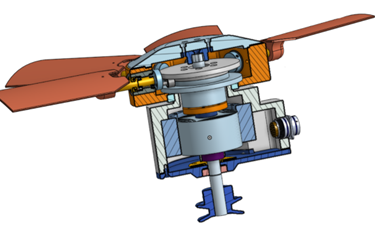
Figure 2 Pulley-driven EMCP fan with lead screw, scotch yoke, slew bearing and reluctance motor for pitch control
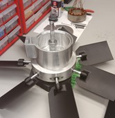
Figure 3 Phase I prototype assembly
The linear actuation achieved by a hydraulic piston embedded in the propeller/fan’s hub is replaced by a variant of an electric spindle (lead screw). This is achieved by spinning a reluctance rotor attached to the spindle’s nut. Spinning the nut when it is threadedly mated to the shaft’s thread causes the nut to move axially which is translated to a scotch yoke via a slew bearing. The scotch yoke’s axial motion causes the blade pitch to change because of a cam follower attached to the fan’s rotatable blade axis that is inserted in the scotch yoke “slot,” which is in fact a continuous opening. A split scotch yoke which bolts together will allow elimination of backlash as the yoke can pinch up against the cam follower.
There is no mechanical coupling between the rotor and stator systems. A radial reluctance rotor is used for pitch control; since it travels axially, the stator electromagnets must have height sufficient to ensure the rotor is exposed to the stator’s electromagnetic force even as the reluctance rotor travels axially a total of 0.185” for 30˚articulation. The pitch of the lead screw presents as mechanical advantage which means the nut is easy to spin and difficult to force linearly – much like the jack on a recreational vehicle.
A magneto-resistive sensor senses the magnetic field of a diametrically magnetized ring magnet affixed on the pitch-manipulating mechanism. The magnet has a working temperature of 250˚C and a Currie temperature of 450˚C. The sensor produces a sine and cosine channel – the combination of which is insensitive to temperature fluctuations (the sensor itself is rated to 150˚C) and changes in the magnet’s field strength due to temperature fluctuations. The axial position is inferred from this same sensor combination. We have manufactured two small PCB mockups with FET’s controlled by a Raspberry PI processor that also receives the magneto-resistive sensor’s signals for closed-loop control of axial position which corresponds directly to blade angle – sinusoidal commutation is used with the radial synchronous reluctance rotor shown in Figure 2.
Table 1 EMCP Kinematic Analysis
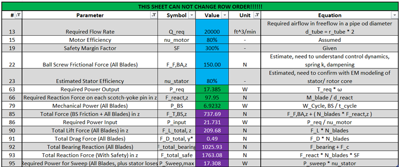
Table 1 demonstrates our anticipated maximum power draw for pitch control which is 17W with torque of 0.33Nm when 20,000 cfm is required. This analysis was done under the assumption of a ball screw but our design has since been simplified to use a lead screw. We have purchased and conducted bench testing of an analogous Flexxaire pneumatic fan and found its pitch control power draw to range from 200W to 720W when the fan is not being spun – these numbers should increase substantially when the fan is under load. This means our pitch-control mechanism ranges from 12 to 42 times as efficient as that of Flexxaire’s without consideration of loading on the Flexxaire fan. We also found Flexxaire’s control to be significantly limited by large hysteresis and that their fan generates large pneumatic ratcheting sounds when pitch control is operated; Flexxaire’s primary offering relates to reversible pitch and much less so on efficiency gains from controllable pitch.
Given this kinematic analysis, we had Dr. Allan Taylor, from the Department of Electrical and Computer Engineering at Kettering University, help us solidify our phase-one pitch-control motor design. Dr. Taylor is an expert in 3-phase motor drive systems and electric machine designs. He helped advance our switched-reluctance design to a synchronous reluctance motor capable of using sinusoidal commutation as shown in Error: Reference source not found. Figure 5 demonstrates anticipated torque for this motor, calculated in simulation, which achieves the necessary 350mNm, required to manipulate pitch at full fan output, with some undesirable to-be-optimized cogging which arises due to a limited number of poles – a future radial motor might have 32 poles rather than the 12 in the current topology. This design can be augmented with ferrite magnets to create a synchronous permanent-magnet-assisted reluctance motor that can generate more than 1 Nm of torque.
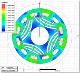
Figure 4 Pitch-control motor's synchronous reluctance design
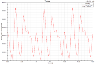
Figure 5 Anticipated torque for pitch-control motor
This motor uses 1010 electric steel laminations which were fabricated by Polaris Laser Laminations Inc. of Chicago, Illinois.
Sinusoidal commutation is used in addition to feedback control on axial displacement, corresponding to blade pitch, as shown in Figure 6.
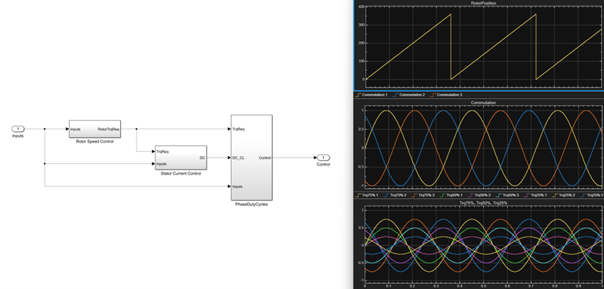
Figure 6 Sinusoidal commutation control system with feedback control on blade pitch
Proof of the feasibility of our fan is in its spinning for pitch control which we hope to achieve with a prototype, presently under fabrication, that will be assembled before the end of Phase I. The detailed description of its operation above may present as complex but it can be explained simply as an electric spindle whose nut is spun by a motor in the stationary system – its axial travel changes the pitch of the blades. It is this simplicity that makes the technology so compelling. We have identified simplifications to even the present design for Phase II which we expect will make the design significantly more compact and versatile (Figure 2’s design is 6” in height – 7” in diameter). We will satisfy the “prototype delivery” aspects of our proposal with a description of our Phase II prototype intent in the next section.
Given the lack of practical controllable pitch solutions and the burdens of the present hydraulics approach we expect we will rapidly gain traction towards a forceful market position in the commercial sector. The axial fan we have designed in Phase I is not far from market readiness. Cooling fans in passenger vehicles are the least application of our fan technology as their cost sensitivities, in light of the vehicle’s motion generating adequate supplementary air flow when travelling at speed, will require strain in how we manufacture our product absent some cleverness which we intend to muster. Whereas large construction and agricultural machinery like excavators and dump trucks will be ideal markets for our product – somewhat like the ground military vehicle market. Mining ventilation takes up nearly 40% of a mine’s power draw and controllable pitch is only used there when fans become very large – leaving the possibility for EMCP to completely revolutionize a mine’s air flow. The potential for all sorts of industrial applications is equally as exciting (as alluded to in the ABB case study2). The reality of our free-market proposition is – we will build it and they will come.
Through iteration, we have also realized we could offer a very low-cost manually-adjusted controllable-pitch fan by omitting the pitch-control motor and limiting such a design to a scotch yoke and threaded nut manipulated by hand operation. This will make the technology feasible at low-cost points for operators not desiring continuous automated pitch control.
The possibilities for drones, both aeronautic and marine, as well as traditional aerospace markets are huge for EMCP. VTOL companies like Uber Elevate are avoiding present hydraulic controllable pitch solutions because of their complexity, cost and weight; EMCP is therefore in a strong position to help invigorate the nasçent electrification of aircraft with both a pareto-optimal pitch control system and a low weight, low cost, non-rare earth motor.